On the Designs of a Paper Airplane
- Cheerful Loh
- Mar 16, 2023
- 11 min read

To preface, this project in particular is a part of my secondary school Physics syllabus. I am sharing this merely due to wanting to publish said information for the benefit of those interested.
Introduction
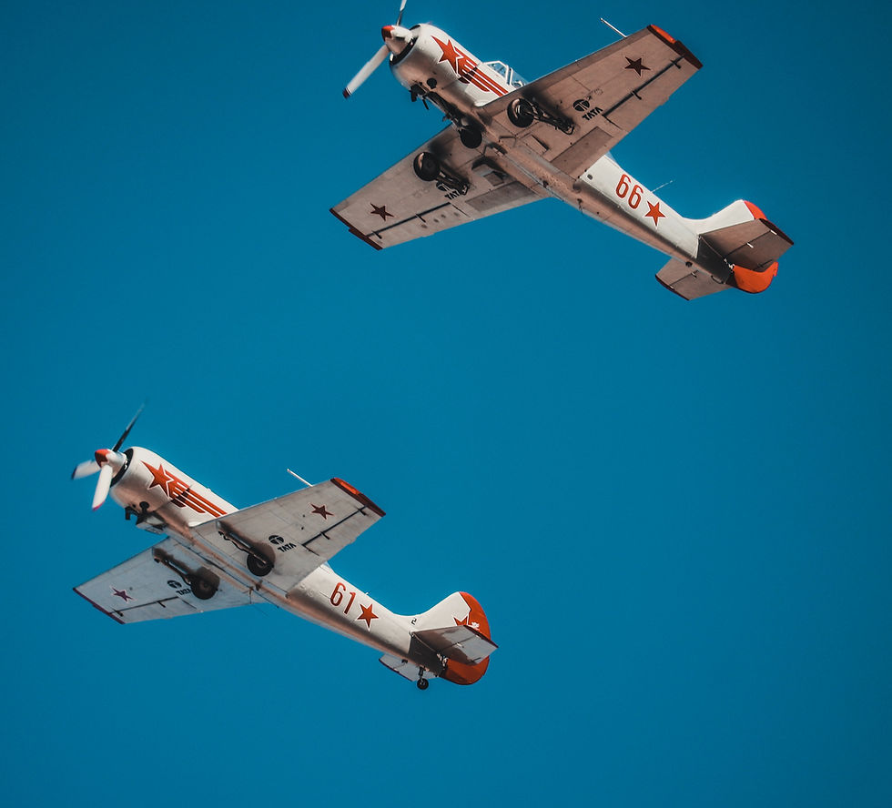
The aviation industry has been a crucial part in society’s development ever since the rapid advancement of biplanes during the First World War. The aeroplane’s contributions, both in terms of civil commodity and in military operations, is undoubtedly a major power in steering humanity’s progress. As much as one would like to deeply analyse modern aeroplanes such as the Airbus A380, it would be ridiculous to burden this task within a secondary school level. Therefore, the basics of aviation and particularly the physics behind this marvel of engineering could be presented in the form of paper airplanes, which has surprising capabilities in showcasing major physics principles in aviation.
The construction of the paper airplane must first begin with understanding the underlying principles behind aviation. This should then be followed by understanding the different types of aircraft capable of flight with paper, hence choosing the suitable class of aircraft for a specific purpose. In accordance with this would be the testing phase of the research, where information and data pertaining to the perfect angle of attack, the rate of change in heights with respect to displacement , the total time airborne, the total horizontal displacement travelled and the tendency of pitch, roll and yaw, should be looked into. Modifications could then be made to necessary sections of the plane to improve the stability and performance of the said aircraft.
Theoretical Analysis
There is a plethora of concepts in physics which should be understood to some extent to design a suitable paper airplane for flight. Those crucial concepts include:
Bernoulli's Principle
Newton's Third Law of Motion
Coanda Effect
Centre of Gravity
Dihedral Effect
Wing Loading and Glide Ratio
Lift Force
Bernoulli's Principle
By definition, Bernoulli’s Principle states that an increase in the speed of an enclosed fluid occurs simultaneously with a decrease in static pressure or hydrostatic pressure along a streamline. The equation of the principle is as follows:
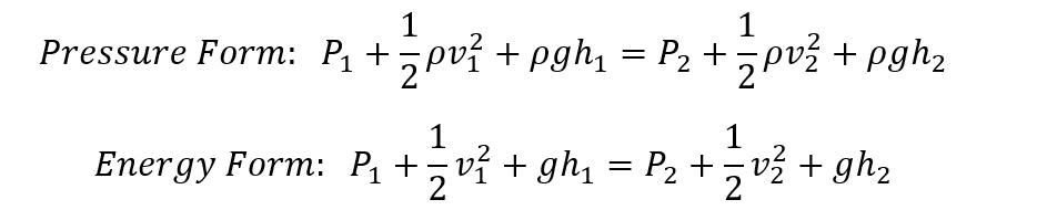
The above equation follows the Principle of Conservation of Energy, hence the addition of three main types of pressures exerted by the fluid equals to a constant. The three pressures are namely, static pressure of a certain enclosed fluid, dynamic pressure (fluid kinetic energy per unit volume) and hydrostatic pressure exerted by the fluid (similar to that of gravitational potential energy. This equivalence principle of energy allows the decrease of pressure when accompanied by an increase in velocity for a horizontal flow of fluid.
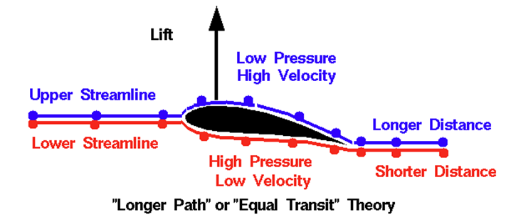
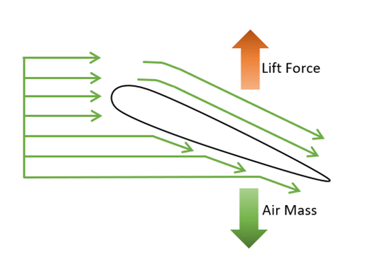
Within the contexts of flight, this phenomenon could be applied to the design of an aerofoil. Since the arch of an aerofoil has a longer length at the top when compared to the bottom, air molecules have to travel at higher velocities to cover that longer length given that time is constant. Henceforth, the high velocity at the top section of the aerofoil produces a region of low pressure while low velocities at the bottom section produces a region of high pressure. This difference in pressure produces an upward lifting force due to different magnitudes of pressure acted upon the surface.
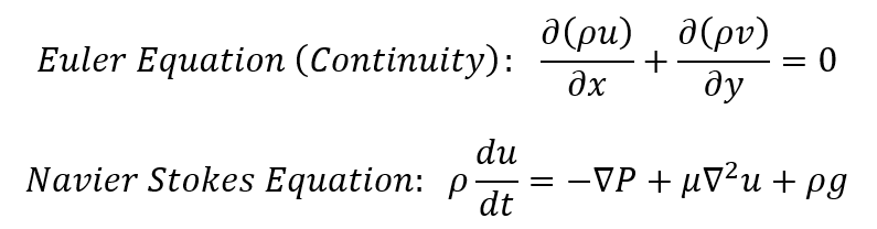
However, despite the use of this principle seems logical, further experimentations and calculations done by the National Aeronautics and Space Administration (NASA) has proved the use of Bernoulli’s Principle to be false and inaccurate (NASA, 2010). The rigorous proofing is done by utilising the Euler Equations, which describes the relationship between the velocity, pressure and density of a moving fluid. These equations are a set of coupled differential equations and are simplifications of the more general Navier-Stokes equation in fluid dynamics. By neglecting the viscosity of the moving fluid, a proper comparison between these two principles could be done. The mentioned partial differential equations are as below for reference; however, it will not be discussed further within the current level of research.
The conclusion of the computational experiments has resulted in three arguments denouncing the use of Bernoulli’s Equation in aerofoils.
Bernoulli’s Equation has the assumption that the upper surface of the structure is always longer than the bottom surface, but this assumption is flawed. This was previously thought to be true because early designs of aerofoils in the 1700s were curved and shaped with a longer distance along the top. Although such designs produce high lift force and flow turning, it is the turning that is important, not the distance of the sections. This could be further proven by modern low-drag aerofoil designs, of which does not obey the above assumption. In addition to this, the theory also does not explain upside-down flight of aircrafts during dogfights and air shows. In this paper’s case, the lengths the upper and lower sections of a paper airplane is equal, therefore effects of Bernoulli’s Principle do not apply.
Although experiments suggest that air molecules do indeed travel at a higher velocity over the top of an aerofoil compared to the bottom, the flow is much faster than the velocity required to ensure air molecules in phase meet up at the trailing edge. Bernoulli’s Equation provides the magnitude of the velocity of the air molecules at the top of the aerofoil, which could then be used to compute the pressure acted upon the aerofoil by using the same principle. Values from this calculation is used to perform the pressure-area calculations, of which answer one gets do not agree with the actual lifting force of the same aerofoil. The lift predicted by Bernoulli’s Equation is less than that of the observation in the experiment because the predicted velocity is too low compared to the actual velocity over the top of the aerofoil. Hence, the entirety of the prediction is not accurate to reality.
It has been stated before that air molecules in phase travel at different speeds and meet at the trailing edge. The problem with this assumption is that this phenomenon does not happen in the physical world. Therefore, the velocity provided by Bernoulli’s Equation is based on a non-physical assumption, hence it has a big difference from the observation.
In summary, the Bernoulli’s Principle should not be the main theory to be referenced during the design and construction of the paper airplane due to its inaccuracy during experimental proof. It should be noted that the principle’s inaccurate nature is due to the wrong application. This principle is specifically engineered to be used in situations involving enclosed fluids as such in a fluid pipe, therefore its use in aerofoil design is uncalled for.
Newton's Third Law of Motion
The famous Newton’s Third Law of Motion states that for every action force there is a reaction force of equal magnitude, but in the opposite direction. In essence, this definition is related back to the Principle of Conservation of Energy as well (Science Learning Hub, 2011). Based on this Newtonian theory of lift, lift force is said to be the reaction force to air molecules striking the bottom of an aerofoil as it manoeuvres through the air. This is aided by a suitable angle of attack, which will in turn add lift force to the aircraft.
However once again, this theory on lift is also deemed incorrect through extensive research by NASA (NASA, 2010). Although the theory is not completely inaccurate, given its effectiveness during high velocity and low air density, it does not provide the correct magnitudes of lift for most normal flight conditions, especially below supersonic speeds.
The inaccuracies of the theory lie in the way air flow is interpreted and used. It is concerned with only the interaction of the lower surface of the aerofoil and the air without taking into account the upper surface interactions. Newtonian lift assumes that all of the flow turning, therefore the lift, is produced solely by the lower surface. In spite of this, experiments done by the agency has debunked the statement. In fact, when considering the downwash produced by a lifting aerofoil, the upper surface usually contributes more flow turning than the lower surface, though the theory ultimately does not predict or explain this observation.
Due to the neglect of action-reaction forces of air molecules striking the upper surface of an aerofoil, it does not predict the negative lift present in calculations when the angle of attack is negative. It must be noted that no vacuum exists on the top of the aerofoil, hence random motions of air molecules will still strike the upper surface and impart momentum to the aerofoil as well. In addition to this, not taking the upper aerofoil surface into account during the theory’s calculations would allow one to assume that two aerofoil designs with the same lower surfaces but very different upper surfaces will generate the same lift force. Unfortunately, this differs wildly to reality. A simple example would be the existence of spoilers between the leading and trailing edges, which are used to change the amount of lift force generated by the wing to manoeuvre the aircraft. The theory, again, does not predict or explain this effect.
When making lift predictions based on the Newtonian lift theory, using a prerequisite knowledge of air density and the number of molecules in a given volume of air (Avogadro’s constant as a reference), the predictions are totally inaccurate when compared to actual measurements during testing. The chief problem of the theory is ultimately due to its neglect on the physical properties of the fluid. Lift is created by turning a moving fluid, not by imparting momentum from the fluid to the aerofoil.
Therefore, the angle of attack, whilst still important for the flight of the paper airplane, should not be interpreted and hence designed with Newton’s Third Law of Motion in mind.
Coanda Effect
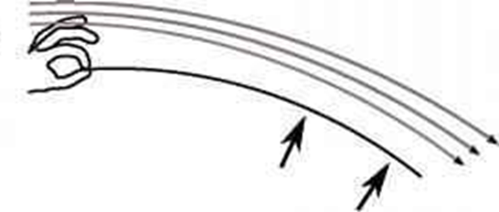
Although lift theory is often erroneously attributed to Bernoulli’s Principle, it is in fact the Coanda Effect that more accurately explains the aerofoil’s purpose during flight. The Coanda effect is the tendency of a moving fluid to attach itself to a surface and flow along it. As a fluid moves across any surface, there is always a certain amount of friction, also known as viscosity, between the fluid and the surface, which tends to slow the moving fluid (Columbia University, 2012). This resistance to the flow of fluids pulls it towards the surface, causing it to flow along a certain shaped path. Discovered by Henri Coanda in 1930, this phenomenon is the best interpretation in fluidics and aerofoil aerodynamics. This effect could be illustrated by a few demonstrations which is usually wrongly described as Bernoulli’s Principle. For example, blowing on the surface of a piece of paper will cause the paper to float and jerk up. In a lot of cases, it is described that faster moving air at the top of the paper creates a region of low pressure compared to that at the bottom of the paper, which causes the piece of paper to float upwards from the pressure difference. In reality, it is the change of momentum of the air stream downwards when following the curved surface that results in an equal and opposite force being produced, of which pushes the paper upwards. Therefore, correlation once again to Newton’s Third Law of Motion, but with a different interpretation.
In terms of its applications onto aerofoils, its geometrical and mathematical descriptions match up perfectly with experimental and observational data.
When an aerofoil moves through the air, surrounding airflows will follow the shape and curvature of the structure, therefore creating a downwards change of momentum at the trailing edge. This downwards force will produce a reaction force of the same magnitude at the opposite direction, which is known as the lift force. Another interpretation of the importance of the Coanda Effect is air molecules will circle around the trailing edge and directly push the structure upwards, which contributes to lift. Nevertheless, gathered data from experiments do indeed match up with this description despite not taking the viscosity and type of airflow (laminar and turbulent) into account. In addition to this, the Coanda Effect also predicts and explains the importance of the correct angle of attack of an aerofoil, which further shows low angle of attack generating little to no lift and high angle of attack causing cavitation or stall.

Referring to the figure, the Coanda Effect comprehensively describes the relationship between angle of attack and lift. At low angles of attack, the amount of lift force produced with Newton’s Third Law of Motion is insufficient to balance gravitational force and produces an upwards resultant force. At a suitable angle of attack, the lift force generated by downwards change of momentum is able to produce an upwards resultant lift force to lift the aircraft. The first two iterations allow air to follow the curvature of the aerofoil because the curvature of the surface is appropriately curved. However, the final high angle of attack will cause cavitation or stall also due to the Coanda Effect. When the aerofoil travels at too high of an angle of attack, the passing air molecules will be unable to adhere to the surface of the wing, therefore losing the impart of momentum to generate lift.
As a general rule, a fluid tends to follow the curvature of a solid surface, but the fluid will break away if it is moving at too high of a velocity or if the surface is too sharply curved, as per shown in the figure. Henceforth, the angle of attack must be taken into consideration when designing the paper airplane to prevent stall or low magnitudes of lift due to the Coanda Effect.
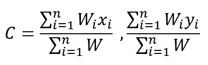
The centre of gravity of an object is defined as a hypothetical point at which the resultant torque due to gravitational forces vanishes. It is a point from which the weight of a body or system may be considered to act (Li, Goodwill, Wang, & Ristroph, 2022). In uniform gravity, this centre is identical to the centre of mass. The equation to get the centre of gravity is as below:
Within the contexts of paper airplane design, the centre of gravity is paramount in determining the pitch and angle of attack of the plane, which is due to the fact that paper airplanes do not possess thrust or pitch manoeuvring systems. By altering the centre of gravity of the said aircraft to be slightly forward, the airplane will be pointing nose down, therefore gaining velocity by travelling with the same direction as gravitational pull. As the velocity increases, higher forces from the previously mentioned Coanda Effect will act on the trailing edge of the plane, which pushes its nose back onto the level pitch. This specific sequence of phenomenon is identical to that of gliders, which utilise the same principles, hence allowing it to maximise its displacement travelled.
However, suitable measures should be put in place to avoid the paper airplane from pointing itself at too low of a pitch to not be able to lift itself back up with the imparted momentum.
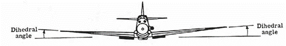
Dihedral Effect The dihedral effect is the amount of roll moment produced in proportion to the amount of sideslip. It represents the upward angle of an aircraft’s wings, which helps to increase the lateral stability in a bank by correcting itself after rolling. If the dihedral angle increases, though stability will increase, lift will decrease and therefore increase drag. When designed properly, the dihedral effect will give enough stability in terms of roll to the paper airplane, whilst also not neglecting the lift efficiency.
Wing Loading and Glide Ratio
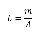
In essence, wing loading is the total mass of an aircraft divided by the area of its wing. This value is used to determine the velocity required to generate enough lift to allow flight for an aircraft. The lower the wing loading, the lower the velocity required to allow sufficient lift.
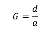
Therefore, since the paper used to fold the aircraft is of constant total mass, it is the area of the wing span that determines the velocity requirements of the aircraft. Generally, a paper airplane would benefit from a low wing loading, which allows it to still be able to fly despite being at low velocities. Besides taking wing loading into consideration, the glide ratio is also affected by the area wingspan of the paper airplane. Glide ratio is the distance of forward travel with respect to the altitude lost in that distance.
For instance, the famous Cessna 172 has a glide ratio of 9:1, which indicates that the aircraft will be able to glide in the air for a distance of 900 metres if its engine malfunctions at an altitude of 100 metres. Modern gliders, however, possesses a glide ratio of 40:1, which helps it stay in the air for a prolonged period of time without requiring thrust from an engine.
Lift Force
Lift is the force that directly opposes the weight of an airplane and holds the airplane in the air. It is a mechanical aerodynamic force produced by the motion of the airplane through the air. Below shows the equation used to calculate the said force, of which will be used to determine the theoretical force imparted to lift the plane.
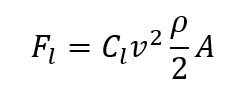
One particular symbol to take note of is C, which represents the coefficient of lift. This dimensionless number is the ratio of lift pressure to the dynamic pressure and area. It is specific to a particular aerofoil and, above the stall, it is proportional to the angle of attack.
References
Columbia University. (2012). Coanda Effect. Columbia Electronic Encyclopedia, 1.
Li, H., Goodwill, T., Wang, Z., & Ristroph, L. (2022). Centre of Mass Location, Flight Modes, Stability and Dynamic Modelling of Gliders. Journal of Fluid Mechanics, 937.
NASA. (2010). Incorrect Theory: Equal Transit Theory. Beginner's Guide to Aeronautics, 2.
NASA. (2010). Incorrect Theory: Skipping Stone Theory. Beginner's Guide to Aeronautics, 2.
NASA. (2010). The Lift Coefficient. Beginner's Guide to Aeronautics, 2.
Science Learning Hub. (2011). The Angle of Attack - Newton's Third Law. WIngs and Lift, 5.

Comments